
- #COMMON CATHODE 7 SEGMENT DISPLAY PIN DIAGRAM HOW TO#
- #COMMON CATHODE 7 SEGMENT DISPLAY PIN DIAGRAM BLUETOOTH#
To power the LED, you connect the cathode to ground and the anode to the voltage supply. The anode is the positive terminal and the cathode is the negative terminal: It includes all of the parts, wiring diagrams, code, and step-by-step instructions for 58 different robotics and internet of things projects that are super fun to build! LED BasicsĪ single LED consists of two terminals, an anode and a cathode.
#COMMON CATHODE 7 SEGMENT DISPLAY PIN DIAGRAM HOW TO#
You should ideally sign into Chrome on: (Select all that apply.The 3-in-1 Smart Car and IOT Learning Kit from SunFounder has everything you need to learn how to master the Arduino.Kumar on Interfacing of Switch and Arduino (Turn ON LED Using a Switch).What can he do within the Bookmark Manager to simplify and organize his list of bookmarks? Unfortunately, he’s bookmarked so many that he’s struggling to find relevant content quickly. Perry has bookmarked a large number of webpages in Chrome while researching class topics. Sarah on EEPROM in Arduino and ESP (ESP8266 and ESP32).
#COMMON CATHODE 7 SEGMENT DISPLAY PIN DIAGRAM BLUETOOTH#
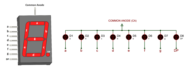
jonas on Bluetooth controlled Robot Car using Arduino.Raman on Display Two Digit Number on 7 Segment.There are many extensions on the Chrome Web Store which are specifically designed for educational use.You should ideally sign into Chrome on: (Select all that apply.).What are the benefits of using Google Groups? (Select all that apply.).What is the most appropriate tool to fulfil this need? Villagarcia has been tasked by the Principal to improve communication and discussion between teachers and support staff. So In order to make this type of 7-segment display work, we should connect the Com pin to the Vcc (+5V typically) and need to ground the required segment pin to turn it on (in simple words give a LOW signal from the Arduino pin to any segment of LED you want to turn it on and +5V to com pin).

In this type, anode pins of all eight segments/LEDs are connected (short-circuited) together. The common anode display is also known as CA display. So In order to make this type of display work, we should connect the Com pin to the Ground pin and need to power the other pins with Vcc (+5V typically). In this type, the cathode pins of all eight segments/LEDs are connected (short-circuited) together. The common cathode display is also known as CC display. Circuit/program designed for Common Anode display cannot be used for Common Cathode or vice versa. OUTPUT on 7 Segment Display SELECTING YOUR 7-SEGMENT DISPLAYħ Segment is either a Common Anode display or a Common Cathode display. Seven Segment PinOut 7 SEGMENTs DISPLAY PIN-CONFIGURATION PIN NUMBERĬontrols the left bottom LED of the 7-segment displayĬontrols the bottom most LED of the 7-segment displayĬonnected to Ground/VCC based on type of displayĬontrols the right bottom LED of the 7-segment displayĬontrols the decimal point LED of the 7-segment displayĬontrols the top right LED of the 7-segment displayĬontrols the top most LED of the 7-segment displayĬontrols the top left LED of the 7-segment displayĬontrols the middle LED of the 7-segment display

The eighth segment (using the DP pin) allows us to show a decimal point. So to make patterns like numbers (0 – 9) or alphabets we just need to power common along with the other segment pin, see in the diagram below. These entire 8 LEDs have one end of their pins pulled out of the module as shown below and the other ends are connected together and pulled out as the Common pin. These 8 LEDs are separated into each segment which can be named as a, b, c, d, e, f, g, DP (decimal point) as shown in the picture below. These displays have 8 LEDs inside it arranged in a manner. The seven segment displays are one of the oldest & efficient types of display used in electronics applications.


 0 kommentar(er)
